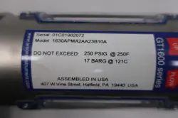
1630APMA2AA23B10A is a configured Brooks variable-area flow meter identified in stored auction history as a 1.4-14 CFM / 1.4-14 SCFM unit with 1/2 inch NPT process connection context. The part-number structure and available Brooks documentation point to the Brooks GT1600 glass-tube variable-area flowmeter family rather than a semiconductor MFC. GT1600 family documentation describes a simple rugged glass-tube flowmeter using a tapered glass tube and float for direct flow indication; exact scale, tube, float, fitting, valve, material, pressure, and calibration details should be verified from the physical meter label
Configurations vary. Verify the exact unit before choosing a replacement.
Application classSemiconductor/high-purity gas delivery
CategoryFlow Control
Specifications
Identification
Configured part number
1630APMA2AA23B10A
Device type
Glass-tube variable area flow meter / rotameter-style flow indicator
Likely family context
Brooks GT1600 glass tube variable area flowmeter family based on 1630 model-code wording and Brooks GT1600 documentation
Observed configuration
Observed flow range
Stored auction titles describe 1.4-14 CFM or 1.4-14 SCFM context
Observed connection
Stored auction titles describe 1/2 inch NPT process connection context
Observed service type
Auction wording identifies the unit as a variable area flow meter, not as a thermal mass flow controller
Operating principle
Variable-area operation
Brooks GT1600 installation documentation describes operation with a tapered glass tube and a float that rises as flow increases through the increasing annular area
Family documentation
GT1600 positioning
Brooks identifies GT1600 glass tube flow meters as simple, rugged variable-area meters for moderate flow applications
Series flow-range context
Brooks GT1600 product documentation lists water flow ranges up to 0.41 gpm / 4,900 lph and air-flow capability for moderate-flow applications depending on tube/float configuration
Construction
Tube and float
GT1600 family documentation describes a tapered glass tube and float as the operating measurement elements
Installation
Flow direction
Variable-area glass-tube flowmeters are installed so fluid enters at the smaller bottom end of the tapered tube and exits at the larger top end
Configuration
Configured-unit rule
Tube code, scale, float material, seal material, valve option, connection, pressure limit, temperature limit, and calibration gas or fluid vary by full configured model code
Inspection
Reuse checks
Inspect glass tube condition, scale readability, float movement, end-block condition, valve operation, threads, seals, and evidence of contamination before reuse
Applications
Application domain
Industrial gas or air flow indication, purge flow indication, panel-mounted variable-area measurement, and general process flow monitoring