Brooks Instrument Four-Channel Microprocessor Control and Readout Unit
About this part
The Brooks Instrument 0154E is a legacy four-channel secondary-electronics unit for powering, reading, and controlling compatible Brooks mass-flow, liquid-flow, and pressure devices. It provides local setpoint control, master/slave blending, valve override, alarms, totalization, remote analog I/O, and RS-232 computer communication. The connected instrument performs the actual flow or pressure measurement and control; the 0154E supplies power, readout, setpoint, and supervisory functions. Brooks no longer offers the 0154 and identifies the 0250 Series as its replacement
Configurations vary. Verify the exact unit before choosing a replacement.
Indoor use; altitude up to 2,000 m (6,562 ft), Pollution Degree 2, Installation Category II
Compliance
Manufacturer-listed approvals
EMC based on EN 50082-2 and EN 50081-1; Low Voltage Directive based on EN 61010-1; CSA-NRTL/C based on CAN/CSA-C22.2 No. 1010.1-92 and ISA S82.01-1994
Configuration-dependent electrical options
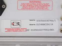
0154E units were factory configured for either ±15 Vdc or +24 Vdc instrument power and for particular signal interfaces. Standard 0–5 Vdc operation does not require the optional I/O board; 0–10 Vdc, 0–20 mA, and 4–20 mA operation requires the optional four-channel converter board and the corresponding jumper settings. A complete configured model code or rear-panel label is therefore required before selecting replacement cables, connected instruments, or signal wiring.
Operating behavior
Independent controlEach of the four channels can operate independently with its own setpoint, engineering-unit label, full-scale value, valve state, alarm settings, and local/remote selection.
Blending modeSlave-channel setpoints are derived from the measured flow or pressure of a selected master channel and the programmed blending ratio.
Power-up behaviorEach channel can restore its memorized setpoint or start at zero; the factory default is zero setpoint after power-up.
Engineering-unit cautionChanging the displayed engineering-unit label does not perform a unit conversion; the corresponding full-scale value must be entered correctly.
Current-I/O groundingThe high-impedance signal grounds are not intended to sink current. For current I/O, the manual requires the mA grounds and readout signal grounds to be tied to power ground as specified.
Supported device families and interconnection cables
The Models 0152/0154 manual identifies these Brooks device families and cables. Cable selection remains dependent on connector and signal configuration.
Connected device or interface
Cable lengths
Brooks cable part numbers
Flomega 5880 and 5890
3 m; 6 m
124Z605ZZZ; 124Z606ZZZ
Mass Flow Series 5850/5860 and Pressure Series 5866 — Netherlands ordering
3 m; 6 m; 12 m
124Z236AAA; 124Z237AAA; 124Z610AAA
Mass Flow Series 5850/5860 and Pressure Series 5866 — USA ordering
5 ft; 10 ft; 25 ft; 50 ft
124Z576AAA; 124Z577AAA; 124Z578AAA; 124Z579AAA
Smart Mass Flow Series 5850S with digital communication
QUANTIM with flow plus density or temperature available
5 ft; 10 ft; 25 ft; 50 ft
124Z906ZZZ; 124Z907ZZZ; 124Z908ZZZ; 124Z909ZZZ
Personal computer RS-232 connection
3 m
124Z901ZZZ
Official 5850EM-to-0154E cable compatibility
A Brooks 5850EM manufacturer manual explicitly names the 0154E and gives separate shielded-cable sets for card-edge and voltage-I/O D-sub versions.
5850EM interface
5 ft
10 ft
25 ft
50 ft
Card edge to 0154E
S124Z669AAA
S124Z539AAA
S124Z562AAA
S124Z670AAA
D-sub, voltage I/O, to 0154E
S124Z576AAA
S124Z577AAA
S124Z578AAA
S124Z579AAA
Channel connector pinout
Pinout for each 15-pin channel connector. Power pins vary with the configured ±15 Vdc or +24 Vdc supply option.
Pin
Direction
Function
1
Output
+15 Vdc or +24 Vdc
2
Input
Flow signal, current
3
Output
Setpoint, current
4
—
Not connected
5
Output
Setpoint, voltage
6
—
Setpoint ground
7
Output
Valve override
8
—
Flow-signal ground
9
—
Reserved
10
Input
Flow signal, voltage
11
—
Not connected
12
—
Power ground
13
Output
+15 Vdc or +24 Vdc
14
Output
−15 Vdc for ±15 V configuration; not connected for +24 V configuration
15
—
Not connected
External valve-control connector pinout
Pinout for the 15-pin external valve-control connector.
Pin
Direction
Function
1
Input
Remote valve override, channel 1
2
—
Not connected
3
Input
Remote valve override, channel 2
4
—
Not connected
5
Input
Remote valve override, channel 3
6
—
Not connected
7
Input
Remote valve override, channel 4
8
—
Not connected
9
Output
+15 Vdc or +24 Vdc
10–14
—
Not connected
15
Output
−15 Vdc for ±15 V configuration; power ground for +24 V configuration
Remote analog connector pinout
Pinout for the 25-pin remote setpoint and measured-signal connector.
Pin
Direction
Function
1
Output
Flow voltage, channel 1
2
Output
Flow current, channel 1
3
Output
Flow voltage, channel 2
4
Output
Flow current, channel 2
5
Output
Flow voltage, channel 3
6
Output
Flow voltage, channel 4
7
Output
Flow current, channel 3
8
Input
Remote voltage setpoint, channel 1
9
Input
Remote voltage setpoint, channel 2
10
Output
Flow current, channel 4
11
Input
Remote voltage setpoint, channel 3
12
—
Not connected
13
Input
Remote voltage setpoint, channel 4
14
—
Flow ground, channel 1
15
Input
Remote current setpoint, channel 1
16
—
Flow ground, channel 2
17
Input
Remote current setpoint, channel 2
18
—
Flow ground, channel 3
19
—
Flow ground, channel 4
20
—
Setpoint ground, channel 1
21
—
Setpoint ground, channel 2
22
Input
Remote current setpoint, channel 3
23
—
Setpoint ground, channel 3
24
Input
Remote current setpoint, channel 4
25
—
Setpoint ground, channel 4
RS-232 connector pinout
The standard computer interface uses a 9-pin D-sub connector.
Pin
Function
1
Not connected
2
TXD — transmitted data
3
RXD — received data
4
Not connected
5
Signal ground
6–9
Not connected
Replacement and software status
Sales statusThe 0152 and 0154 secondary-electronics devices are no longer available for sale from Brooks Instrument.
Manufacturer replacementBrooks identifies the 0250 Series as the replacement family; the 0254 is the four-channel member.
Mechanical retrofitThe 0254 rack-mount kit can adapt the replacement controller and power supply to the tabletop enclosure used for the 0152/0154.
Software supportBrooks Smart DDE and Brooks LabVIEW DLL documentation continue to identify Models 0152 and 0154 as supported secondary-electronics devices.