Brooks MF51X NEMA 4X/IP66 Thermal Mass Flow Controller
About this part
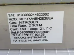
Brooks MF51XA4BN2E2BEA is a configured MF51X thermal mass flow controller with an integral solenoid control valve. The MF51X belongs to the rugged Mfx branch, documented with welded-sensor construction, NEMA 4X/IP66 protection, and hazardous-location approvals. Brooks specifies a 10–100 slpm nitrogen-equivalent full-scale envelope for the MF51 base model; the configured gas, full-scale setting, process connections, seal material, and other suffix-selected options require the unit label or Brooks order record
Configurations vary. Verify the exact unit before choosing a replacement.
Application classIndustrial automation and process equipment
CategoryFlow Control
Specifications
Identification
Manufacturer
Brooks Instrument
Product series
Brooks Mf Series, Mfx branch
Base model
MF51X
Function
Device function
Thermal gas mass-flow measurement and closed-loop control using an integral solenoid control valve and remote setpoint
Performance
Documented MF51 full-scale envelope
10–100 slpm nitrogen equivalent at 0°C and 101 kPa (760 Torr); this does not establish the configured unit's full-scale range or calibration gas
Control/usable range
50:1 (Mf Series specification)
Accuracy
±1% of full scale including linearity at calibrated conditions (Mf Series specification)
Repeatability
0.25% of rate (Mf Series specification)
Response time
Less than 6 seconds to within 2% of full scale of the final value for a 0–100% command change
Pressure
Maximum operating pressure
MF51 model rating: 1000 psi (68 bar)
Controller differential pressure
MF51 model: 10–50 psid
Environmental
Ambient and gas temperature
5–65°C (41–149°F)
Construction
Sensor construction
Welded sensor assembly for the Mfx branch
Enclosure protection
NEMA 4X and IP66 watertight construction
Wetted-material options
Stainless steel with Viton fluoroelastomer or Buna-N; Kalrez optional. The exact seal option is not established for this configured identifier
Connections
Documented MF51 process-connection options
9/16-18 UNF, 1/4-inch tube compression, 3/8-inch tube compression, 1/4-inch VCR, or 1/4-inch VCO; exact configured connection not established
Electrical
Power requirement
MF51: 22–28 Vdc governing range; 309 mA at 22 Vdc and 370 mA at 28 Vdc
Setpoint inputs
4–20 mA into 75 ohms or 0–5 Vdc into 220 kΩ
Flow outputs
0/4–20 mA and 0–5 Vdc outputs are documented; current-output zero selection is configurable
Cable/conduit entry options
Pg11 watertight cable gland; the installation manual also documents a 1/2-inch FNPT conduit-fitting option
Approvals
Mfx hazardous-location classification
Non-incendive Class I, Division 2, Groups A, B, C and D; Class II, Division 2, Groups F and G; suitable for Class III, Division 2. Applicable approval markings should be confirmed on the installed unit
What Does MF51XA4BN2E2BEA Mean?
Brooks documentation supports the base-model interpretation but does not provide a verified ordering key for the configured suffix.
Segment
Field
Interpretation
MF51
Base model
Mf Series thermal mass flow controller with an integral control valve; documented 10–100 slpm nitrogen-equivalent full-scale envelope
X
Product branch
Mfx rugged/hazardous-location branch with welded-sensor construction and NEMA 4X/IP66 enclosure
A4BN2E2BEA
Configured option suffix
A verified Brooks ordering-code key was not available. Do not assert gas, full-scale range, fittings, seals, electrical option, calibration reference, or mounting orientation from these characters alone
MF Series Terminal-Strip Connections
Family-level terminal assignments from the Brooks data sheet. Valve-override and command terminals apply to controller models such as MF51X.
Terminal Strip
Terminal
Label
Function
TB-1
1
VSUP
Positive supply voltage
TB-1
2
SUPCOM
Supply common
TB-1
3
NC
Not used
TB-1
4
SUPCOM
Signal common
TB-1
5
VSIG
Voltage flow-signal output
TB-1
6
ISIG
Current flow-signal output
TB-2
1
NC
Not used
TB-2
2
GND
Chassis ground
TB-2
3
NC
Not used
TB-2
4
VREF
+5 Vdc reference output
TB-2
5
VOR
Valve-override input
TB-2
6
NC
Not used
TB-2
7
CMDCOM
Command common
TB-2
8
VCMD
Voltage setpoint input
TB-2
9
ICMD
Current setpoint input
Configuration Boundary
MF51X documentation defines the controller's operating envelope and branch construction. The full configured identifier does not independently establish the calibration gas, calibrated full-scale flow, fitting selection, elastomer, current-output setting, calibration reference conditions, or mounting orientation. Those values are read from the manufacturer label, calibration certificate, or Brooks order acknowledgment.
Operating and Safety Notes
A command below 1% of full scale causes the controller valve to close fully; the valve-override circuit can latch it fully open or closed.
After exposure to toxic, pyrophoric, flammable, or corrosive gas, purge the controller thoroughly with dry inert gas before disconnecting it.
Do not exceed the documented pressure, temperature, or electrical ratings.
Mounting attitude was an order-time consideration for optimum performance; re-zero the instrument under its installed operating conditions.